Grid commands
The active 2D view can be set to display a grid, and the cursor can be made to snap to the points of the grid, in the following contexts:
-
2D imports
-
Component Modeller
-
Drafting
- Plant Modeller 2D drawings
- Isometric and spool drawings
-
P&ID
Selecting Navigate from the context menu of the view displays the following grid specific commands.
Move to nearest grid point/Release (F6)
This command moves to the nearest grid point.
Grid (F7)
This command shows or hides the grid.
Ortho (F8)
This command enables or disables orthogonal movements. When enabled, movement is restricted to the U or V direction.
Note: This command is also available when using a Move command on a 3D object.
Snap (F9)
This command enables or disables snapping. When enabled, movement occurs in increments determined by the snap spacing values specified in the settings.
Grid, Snap & Cursor step settings (F10)
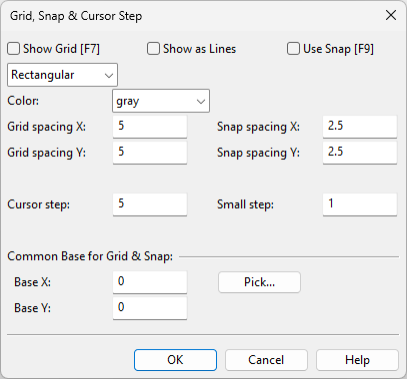
Opens the Grid, Snap & Cursor Step dialog where you can specify the following settings for the active drawing or diagram.
-
Show Grid (F7) – Select this option to display the grid. Also choose the grid type: Rectangular, Isometric Top, Isometric Left, or Isometric Right.
-
Show as Lines – Select this option to display the grid as lines instead of dots.
-
Use Snap (F9) – Select this option to allow the cursor to snap to the grid.
-
Color – Select the color of the grid.
-
Grid spacing X, Y – Specify the distance between the grid points along the X and Y axes.
-
Snap spacing X, Y – Specify the snapping distance along the X and Y axes. For example, if you set the snap spacing to be half of the grid spacing, you can snap to the middle of two grid points.
-
Cursor step – Specify a grid spacing multiplier to define how much the cursor moves each time an arrow button is pressed in Default (-) cursor step mode. Value range 0–10000, default is 5 times the grid spacing.
-
Small step – Specify a grid spacing multiplier to define how much the cursor moves each time an arrow button is pressed in Small (9) cursor step mode. Value range 0–10000, default is 1 (equal to grid spacing).
-
Base X, Y – Specify an offset for the starting point of the grid/snapping area, either manually or by using the Pick tool.
